
Page 165 - ingenioren
P. 165
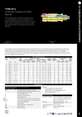
TYPE CR-C                                                                                                ACCESSORIES  Ex CABLEGLANDS &
        Universal	Compound	Cable

        Glands


        “CR-C Type” glands, certified Flameproof Ex d,
        Increased Safety Ex e, Dust Protected Ex ta &
        Restricted Breathing Ex nR are suitable for use in
        Zone 1, Zone 2, Zone 20, Zone 21, Zone 22 and in
        Gas Groups IIA, IIB, IIC and Dust Groups IIIA, IIIB                                                        Ex-CABLEGLANDS & ACCESSORIES
        and IIIC.


         PRODUCT                                                         PRODUCT
      INFORMATION                                                          IMAGE


        Occasionally	referred	to	as	“potting	glands”,	they	provide	a	compound	barrier	Ex	d	&	IP	seal	on	the	cable	inner	cores,	eliminating	damage	to	cables	that
        exhibit	“cold	flow”	characteristics	and	an	environmental	seal	on	the	outer	sheath.	The	unique	features	include,	“CROCLOCK®”,	the	non	reversible	multi
        clamping	system	for	wire,	braid	and	tape	armoured	cables	and	Peppers	T1000,	the	sealing	compound	that	enables	a	quick	and	easy	installation.
        The	innovative	barrier	chamber	provides	a	cable	acceptance	that	is	on	average	17%	greater	than	other	designs.	The	gland	maintains	IP66	&	IP68	to	100
        metres	and	is	deluge	proof	without	the	use	of	an	additional	seal	or	deluge	boot.	It	is	supplied	with	an	IP	O-ring	seal	as	standard	on	metric	entry	threads	and
        options	are	available	for	use	with	lead	sheath.
                                                CABLE GLAND SELECTION TABLE
         Gland  Entry Thread Size  ISO      Cable Acceptance Details   Armour  Normal  Dimensions/Weight  Metric
         Size                Thread   Cable Inner Sheath (C)  Cable Outer Sheath (D)  Acceptance  Protrusion  (Metric)  Thread
                             Length                                    Range  Length (L)             Shroud
                              (B)  Number   Max Ø   Max Inner  Standard  Reduced    Across  Across  Weight  Size
              Metric   NPT        of Cores Over Cores  Sheath  Min  Max  Min  Max    Flats  Corners (A)  (kgs)
          16  M20x1.5  1/2” or 3/4”  16  15  10.4  11.7  9.0  13.5  6.7  10.3  0.15-1.25  79  25.4  28.0  0.177  EL24
         20S  M20x1.5  1/2” or 3/4”  16  35  10.4  11.7  12.9  16.0  9.4  12.5  0.15-1.25  79  25.4  28.0  0.166  EL24
          20  M20x1.5  1/2” or 3/4”  16  40  12.5  14.0  15.5  21.1  12.0  17.6  0.15-1.25  79  30.0  33.0  0.245  EL30
          25  M25x1.5  3/4” or 1”  16  60  17.8  20.0  20.3  27.4  16.8  23.9  0.15-1.60  89  37.6  41.4  0.402  EL38
          32  M32x1.5  1” or 1 1/4”  16  80  23.5  26.3  26.7  34.0  23.2  30.5  0.15-2.00  110  46.0  50.6  0.738  EL46
          40  M40x1.5  1 1/4” or 1 1/2”  16  130  28.8  32.2  33.0  40.6  28.6  36.2  0.20-2.00  110  55.0  60.5  1.079  EL55
         50S  M50x1.5  1 1/2” or 2”  16  200  34.2  38.2  39.4  46.7  34.8  42.4  0.20-2.50  125  65.0  71.5  1.455  EL65
          50  M50x1.5  2”     16   400   39.4   44.1  45.7  53.2  41.1  48.5  0.20-2.50  125  65.0  71.5  1.366  EL65
         63S  M63x1.5  2” or 2 1/2”  19  400  44.8  50.1  52.1  59.5  47.5  54.8  0.30-2.50  125  80.0  88.0  2.157  EL80
          63  M63x1.5  2 1/2”  19  425   50.0   56.0  58.4  65.8  53.8  61.2  0.30-2.50  125  80.0  88.0  2.035  EL80
         75S  M75x1.5  2 1/2” or 3”  19  425  55.4  62.0  64.8  72.2  60.2  68.0  0.30-2.50  130  90.0  99.0  2.399  EL90
          75  M75x1.5  3”     19   425   60.8   68.0  71.1  78.0  66.5  73.4  0.30-2.50  130  90.0  99.0  2.313  EL90
          80  M80x1.5  3” or 3 1/2”  25  425  64.4  72.0  77.0  84.0  71.9  79.4  0.45-3.15  162  104.0  115.2  4.763  EL104
          85  M85x1.5  3” or 3 1/2”  25  425  69.8  78.0  79.6  90.0  75.0  85.4  0.45-3.15  162  104.0  115.2  4.122  EL104
          90  M90x1.5  3 1/2” or 4”  25  425  75.1  84.0  88.0  96.0  82.0  91.4  0.45-3.15  162  114.0  125.7  5.114  EL114
         100  M100x1.5  3 1/2” or 4”  25  425  80.5  90.0  92.0  102.0  87.4  97.4  0.45-3.15  162  114.0  125.7  4.356  EL114
                                                   All dimensions in mm
                                                              Features:
         Example Part Numbering CR-1BCK1/NP/20/050NPT
         (See below for details)                              •	  Exd/Exe	Double	compression	barrier	gland
                                                                  IP66,	68	(100metres	for	7	days)		deluge
                                                              •
         CR-C             Type of gland featuring “CROCLOCK”, single   •	  Featuring	Peppers	T-1000	fast	curing	compound
                          orientation clamping, Compound (Barrier) Inner seal   •	  Temperature	rating	-60°	to	+135°C
                          & Silicone Elastomeric Outer Seal   •	  Brass	or	stainless	steel
         2                For Lead Sheath Cables
         B                Brass (B) / Stainless Steel (S)      Technical information  EN 60079-0, EN 60079-1, EN 60079-7, EN
                                                               Compliance standard
                          Reduced Bore Seal
       Options R          PVC Shroud (C) - PCP Shroud (P) - LSOH Shroud (3)    60079-15, EN 60079-31, IEC 60079-0, IEC
         C
                                                                               60079-1, IEC 60079-7, IEC 60079-15, IEC
         K or V
                          Locknut, Earth Tag & Nylon (K) or Fibre (V) IP Washer
         S                Including Serrated Washer            IP Rating       60079-31 and IEC 60529
                                                                               IP66 & IP68 (100 metres - 7 days),
         1                Quantity per kit                                     NEMA 4X & DTS01 1991
         NP               Nickel Plated (NP) - Zinc Plated (ZP)  Operating temperature -60°C to +135°C
         20               Gland shell size                     Materials       Brass or Stainless Steel
         M20              M20 Entry Thread                     Plating         Nickel, Zink
         IP
         66/68                                                                                                     03