
Page 162 - ingenioren
P. 162
Ex CABLEGLANDS & ACCESSORIES
Ex-CABLEGLANDS & ACCESSORIES
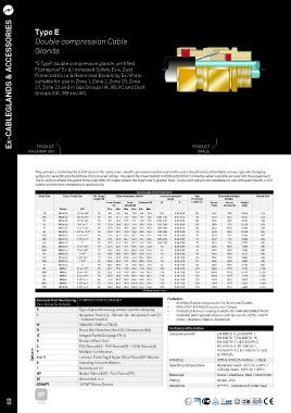
Type E
Double compression Cable
Glands
“E Type” double compression glands, certified
Flameproof Ex d, Increased Safety Ex e, Dust
Protected Ex ta & Restricted Breathing Ex nR are
suitable for use in Zone 1, Zone 2, Zone 20, Zone
21, Zone 22 and in Gas Groups IIA, IIB, IIC and Dust
Groups IIIA, IIIB and IIIC.
PRODUCT PRODUCT
INFORMATION IMAGE
They provide a controlled Ex d & IP seal on the cable inner sheath, an environmental seal on the outer sheath and a detachable armour specific clamping
system for wire (W) and braid/tape (X) armoured cables. The gland has been tested to IP66 and IP68 to 50 metres when suitable secured into the equipment.
The IE version allows the gland to be used with HV cables where the fault load is greater than 10.4kA and options are available for use with lead sheath, LSOH
cables and extreme temperature applications.
CABLE GLAND SELECTION TABLE
Gland Size Entry Thread Size ISO Thread Cable Acceptance Details Armour Acceptance Max Dimensions/Weight Shroud Size
Length (B) Range Protrusion (Metric)
Inner Sheath Outer Reduced (D) W X Length (L) Across Across Weight
(C) Sheath (D) Flats Corners (A) (kgs)
Metric NPT Min Max Min Max Min Max
16 M20x1.5 1/2” or 3/4” 16 4.0 8.4 8.4 13.5 4.9 10.3 0.9 0.15-0.35 58 24.0 26.5 0.154 L24
20S M20x1.5 1/2” or 3/4” 16 8.0 11.7 11.5 16.0 9.4 12.5 0.90-1.25 0.15-0.35 58 24.0 26.5 0.125 L24
20 M20x1.5 1/2” or 3/4” 16 6.7 14.0 15.5 21.1 12.0 17.6 0.90-1.25 0.15-0.50 58 30.0 33.0 0.180 L30
25 M25x1.5 3/4” or 1” 16 13.0 20.0 20.3 27.4 16.8 23.9 1.25-1.60 0.15-0.50 58 38.0 41.4 0.256 L38
32 M32x1.5 1” or 1 1/4” 16 19.0 26.3 26.7 34.0 23.2 30.5 1.60-2.00 0.15-0.55 65 46.0 50.6 0.400 L46
40 M40x1.5 1 1/4” or 1 1/2” 16 25.0 32.2 33.0 40.6 28.6 36.2 1.60-2.00 0.20-0.60 72 55.0 60.5 0.649 L55
50S M50x1.5 1 1/2” or 2” 16 31.5 38.2 39.4 46.7 34.8 42.4 2.00-2.50 0.20-0.60 73 65.0 71.5 0.940 L65
50H M50x1.5 1 1/2” or 2” 16 31.5 38.2 45.7 53.2 41.1 48.5 2.00-2.50 0.20-0.60 73 65.0 71.5 0.940 L65
50 M50x1.5 2” 16 36.5 44.1 45.7 53.2 41.4 48.5 2.00-2.50 0.30-0.80 73 65.0 71.5 0.707 L65
63S M63x1.5 2” or 2 1/2” 19 42.5 50.1 52.1 59.5 47.5 54.8 2.5 0.30-0.80 76 80.0 88.0 1.369 L80
63H M63x1.5 2” or 2 1/2” 19 42.5 50.1 58.4 65.8 53.8 61.2 2.5 0.30-0.80 76 80.0 88.0 1.369 L80
63 M63x1.5 2 1/2” 19 49.5 56.0 58.4 65.8 53.8 61.2 2.5 0.30-0.80 76 80.0 88.0 1.123 L80
75S M75x1.5 2 1/2” or 3” 19 54.5 62.0 64.8 72.2 60.2 68.0 2.5 0.30-1.00 82 90.0 99.0 1.660 L90
75H M75x1.5 2 1/2” 19 54.5 62.0 71.1 78.0 66.5 73.4 2.5 0.30-1.00 82 90.0 99.0 1.660 L90
75 M75x1.5 3” 19 60.5 68.0 71.1 78.0 66.5 73.4 2.5 0.30-1.00 82 90.0 99.0 1.310 L90
80 M80x2 3” or 3 1/2” 25 62.2 72.0 77.0 84.0 71.9 79.4 3.15 0.45-1.00 110 104.0 115.2 2.718 L104
80H M80x2 3” or 3 1/2” 25 62.2 72.0 79.6 90.0 75.0 85.4 3.15 0.45-1.00 110 104.0 115.2 2.718 L104
85 M85x2 3” or 3 1/2” 25 69.0 78.0 79.6 90.0 75.0 85.4 3.15 0.45-1.00 110 104.0 115.2 2.326 L104
90 M90x2 3 1/2” or 4” 25 74.0 84.0 88.0 96.0 82.0 91.4 3.15 0.45-1.00 110 114.0 125.7 2.852 L104
90H M90x2 3 1/2” or 4” 25 74.0 84.0 92.0 102.0 87.4 97.4 3.15 0.45-1.00 110 114.0 125.7 2.852 L104
100 M100x2 3 1/2” or 4” 25 82.0 90.0 92.0 102.0 87.4 97.4 3.15 0.45-1.00 110 114.0 125.7 2.496 L114
All dimensions in mm
Features:
Example Part Numbering E1WBFCK1/NP/20/050NPT
(See below for details) • Exd/Exe Double compression for Armoured Cables
•
IP66, IP67 & IP68 (50 metres for 7 days)
E Type of gland featuring armour specific clamping • Dedicated Armour Locking Suitable for SWA (W) SWB/STA (X)
1 Neoprene Seals (1) - Silicone (3) - Neoprene/Lead (2) • Available with optional silicone seal for use at -60°to +180°C
- Silicone/Lead (4) • Brass, Stainless Steel or Aluminium
W SWA (W) / SWB or STA (X)
B Brass (B) / Stainless Steel (S) / Aluminium (HA) Technical information
Compliance with EN 60079-0, EN 60079-1,
IE Integral Earth (See page TR-3)
EN 60079-7, EN 60079-15,
R Reduced Bore Seal EN 60079-31, IEC 60079-0,
C PVC Shroud (C) - PCP Shroud (P) - LSOH Shroud (3) IEC 60079-1, IEC 60079-7,
IEC 60079-15, IEC 60079-31 and
Options F K or V Multiple Certification IEC 60529.
Locknut, Earth Tag & Nylon (K) or Fibre (V) IP Washer
S Including Serrated Washer IP Rating IP66 & IP68 (35 metres - 7 days)
Operating temperature
Neoprene Seals -35°C to +90°C /
1 Quantity per kit Silicone Seals -60°C to +180°C
NP Nickel Plated (NP) - Zinc Plated (ZP) Materials Brass / Stainless Steel / Aluminium
20 Gland shell size Plating Nickel, Zink
050NPT 1/2”NPT Entry Thread Variations D****F - Omission of Outer Seal
IP
03 66/68