
Page 163 - ingenioren
P. 163
Type A ACCESSORIES Ex CABLEGLANDS &
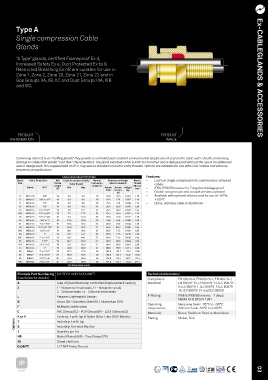
Single compression Cable
Glands
“A Type” glands, certified Flameproof Ex d,
Increased Safety Ex e, Dust Protected Ex ta &
Restricted Breathing Ex nR are suitable for use in
Zone 1, Zone 2, Zone 20, Zone 21, Zone 22 and in
Gas Groups IIA, IIB, IIC and Dust Groups IIIA, IIIB Ex-CABLEGLANDS & ACCESSORIES
and IIIC.
PRODUCT PRODUCT
INFORMATION IMAGE
Commonly referred to as “stuffing glands” they provide a controlled pull resistant environmental displacement seal on the cable outer sheath, minimising
damage to cables that exhibit “cold flow” characteristics. The gland maintains IP66 & IP68 to 50 metres and is deluge proof without the use of an additional
seal or deluge boot. It is supplied with an IP O-ring seal as standard on metric entry threads. Options are available for use with LSOH cables and extreme
temperature applications.
CABLE GLAND SELECTION TABLE Features:
Gland Entry Thread Size ISO Cable Acceptance Details Normal Dimensions/Weight Metric • Exd/Exe Single compression for unarmored or armored
Size Thread Outer Sheath Protrusion (Metric versions) Thread cables
Length Length (L) Shroud
Metric NPT (B) Min Max Across Across Weight Size • IP66, IP68 (50 metres for 7 days) and deluge proof
Flats Corners Kgs
(A) • Double compression and conduit versions optional
12 M12x1.5 3/8” 16 0.9 6.0 26 19.0 20.9 0.041 L19 • Available with optional silicone seal for use at -60°to
12 M16x1.5 3/8” or 1/2” 16 0.9 6.0 26 25.4 27.9 0.072 L24 +180°C
12 M20x1.5 1/2” 16 0.9 6.0 26 25.4 27.9 0.094 L24 • Brass, stainless steel or aluminium
16 M16x1.5 1/2” 16 4.0 8.4 33 25.4 28.0 0.078 L24
16 M20x1.5 1/2” or 3/4” 16 4.0 8.4 33 25.4 28.0 0.078 L24
20S M20x1.5 1/2” or 3/4” 16 7.2 11.7 33 25.4 28.0 0.101 L24
20 M20x1.5 1/2” or 3/4” 16 9.4 14.0 33 30.0 33.0 0.127 L30
25 M25x1.5 3/4” or 1” 16 13.5 20.0 33 37.6 41.4 0.166 L38
32 M32x1.5 1” or 1 1/4” 16 19.5 26.3 33 46.0 50.6 0.244 L46
40 M40x1.5 1 1/4” or 1 1/2” 16 23.0 32.2 37 55.0 60.5 0.396 L55
50S M50x1.5 1 1/2” or 2” 16 28.1 38.2 37 65.0 71.5 0.558 L65
50 M50x1.5 2” 16 33.1 44.1 37 65.0 71.5 0.438 L65
63S M63x1.5 2” or 2 1/2” 19 39.2 44.1 37 65.0 71.5 0.438 L65
63 M63x1.5 2 1/2” 19 46.7 56.0 37 80.0 88.0 0.664 L80
75S M75x1.5 2 1/2” or 3” 19 52.1 62.0 37 90.0 99.0 0.924 L90
75 M75x1.5 3” 19 58.0 68.0 37 90.0 99.0 0.714 L90
80 M80x2 3” or 3 1/2” 25 62.2 72.0 50 104.0 115.2 1.514 L104
85 M85x2 3” or 3 1/2” 25 69.0 78.0 50 104.0 115.2 1.332 L104
90 M90x2 3 1/2” or 4” 25 74.0 84.0 50 114.0 125.7 1.622 L114
100 M100x2 3 1/2” or 4” 25 82.0 90.0 50 114.0 125.7 1.523 L114
All dimensions in mm
Example Part Numbering A2LBFCK1/NP/20/050NPT Technical information
(See below for details) Compliance EN 60079-0, EN 60079-1, EN 60079-7,
A Type of gland featuring controlled displacement sealing standard EN 60079-15, EN 60079-31, IEC 60079-
2 1 - Neoprene/Lead seals / 2 - Neoprene seals 0, IEC 60079-1, IEC 60079-7, IEC 60079-
3 - Silicone seals / 4 - Silicone/Lead seals 15, IEC 60079-31 and IEC 60529
L Peppers Lightweight Design IP Rating IP66 & IP68 (50 metres - 7 days),
NEMA 4X & DTS01 1991
B Brass (B) / Stainless Steel (S) / Aluminium (HA)
Operating Neoprene Seals -35°C to +90°C
F Multiple Certification temperature Silicone Seals -60°C to +180°C
C PVC Shroud (C) - PCP Shroud (P) - LSOH Shroud (3) Materials Brass, Stainless Steel or Aluminium
K or V Locknut, Earth Tag & Nylon (K) or Fibre (V) IP Washer Plating Nickel, Zink
Options T S Including Earth Tag
Including Serrated Washer
1 Quantity per kit
NP Nickel Plated (NP) - Zinc Plated (ZP)
20 Gland shell size
050NPT 1/2”NPT Entry Thread
IP
66/68 03